| SECTION G MAYDOWN TECHNICAL INFORMATION |
| The following pages include technical information on Maydown products, including ramping angles, counterbore details and circular interpolation sizes. Included are some useful demonstration examples of our more popular cutters and a problem solving chart for milling inserts. We are also showing recommended speeds and feeds for indexables, HSS and solid carbide cutters. | |
 |
|
| CONTENTS | |
| G2 Minimum pre-drilled hole sizes prior to sinking for cutters from section A & B. G3 Ramping angles for Maydown end mills from section A & B. G4 Ramping angles for Maydown face mills from section A & B. G5 Circular interpolation for Maydown face mills from section A & B. G6 Hi-speed router cutting data. G7 Stresses on cutting edges when milling. G8 Problem solving chart for milling applications. G9 Maydown formulae for milling calculations. G10 Recommended speeds and feeds for Maydown and competitor milling cutters. G11 Recommended speeds and feeds for copy milling cutters and round Insert facemills. G12 Cutting speed chart for use with small diameter end mills from pages A2 & A7. G13 Demonstration examples for Maydown 90° and 45° Super Aludex milling cutters. G14 Recommended speeds and feeds for Maydown XL indexable cutters. G15 Demonstration examples for Maydown high shear facing cutters. G16 to G19 Total reaches below shank for the copy milling range. G20 Speeds and feeds for Multi-Edge RipFeed cutters. G21 Speeds and feeds for solid carbide end mills and slot drills. G22 Calculations when using ball nosed copy milling cutters. G23 to G24 Speeds and feeds for Triplicut high speed steel. |
|
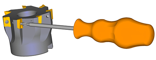
| INSERT MOUNTING DETAILS |
| For all Maydown cutters with centre screw insert fixing To ensure true insert location the pocket must be clean and free from swarf. Press firmly with the thumb on the rear of the insert, position the screw and tighten home, keeping the screwdriver in line with the screw. |
 |